| Version 3 (modified by , 12 years ago) (diff) |
|---|
Infrastructure & Assembly
We used the following components to build up our client infrastructure. Note that links provided are just proposals for your convenience, other components will also work. Depending on your specific needs, there are several different methods to build and use your flarmradar groundstation. For all cases you need:
- a FLARM device
- a Raspberry PI
All revisions of the Pi can be used for Flarmradar ground stations. Depending on the revision you choose to use, wiring instructions differ slightly.
- a Power supply
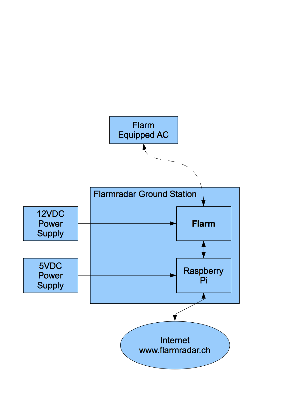
Depending on your specific requirements, creativity, etc. there are a lot of different ways to supply your Flarmradar ground station with power. We gathered experience with a few ways and will describe the different setups below. Flarm devices typically run on 12VDV power supply. All Raspberry Pi run on 5VDC. Hence you will have to generate and supply two different voltages within your ground station.
- Power supply from grid available
- Use two standard power converter (e.g. RS-Online) to supply 12VDC and 5VDC
- For battery powered FGS, use a 12V battery as used in most gliders
- To connect the FGS to external power supply or battery, use a connector, which is protected against polarity reversal (e.g. RS-Online)
- To protect your Flarm against over current, a 500mA fuse should be installed in the power supply route to the Flarm (e.g. RS-Online)
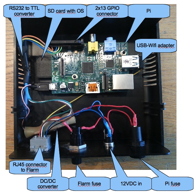
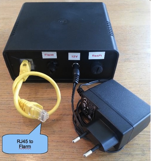
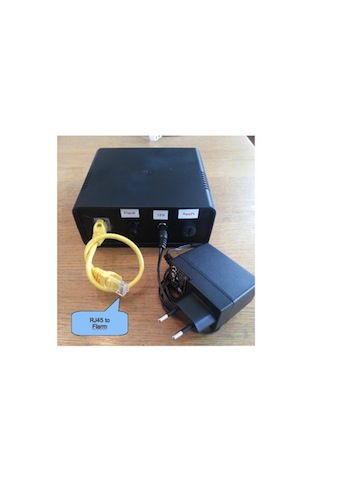
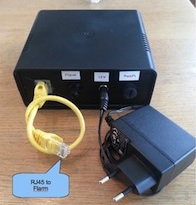
- To connect your Flarm to the FGS, we recommend installing a RJ45 connector on the FGS front panel and to use a short network cable to connect the FGS to the Flarm
- For pin assignment of the RJ45 please consult Flarm Installation Manual
- Wiring instructions: 12V DC In --> Flarm fuse --> RJ45 connector --> network cable --> Flarm
- Alternative way of Flarm power supply: update cable
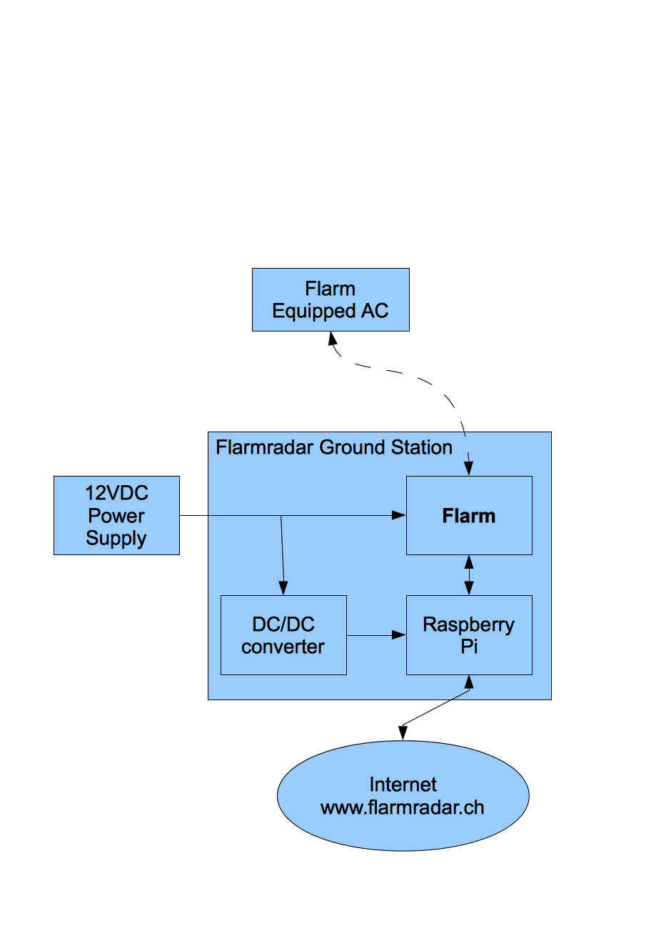
- Raspberry is running on a 5V power supply therefore the 12V power supply must be converted to 5V for the Pi.
- Power conversion can be performed using DC/DC converter. Make sure the DC/DC converter can deliver at least 1A.
- To protect your Pi against over current, a 500mA fuse should be installed in the power supply route to the Pi (e.g. RS-Online)
- Use a Micro-USB connector to feed the power into your pi
- Wiring instructions: 12V DC IN --> Pi Fuse --> DC/DC converter --> Micro-USB connector --> Pi
- Alternative way of Pi power supply: A USB charger to power the Raspberry, just make sure it can deliver at least 1000mA
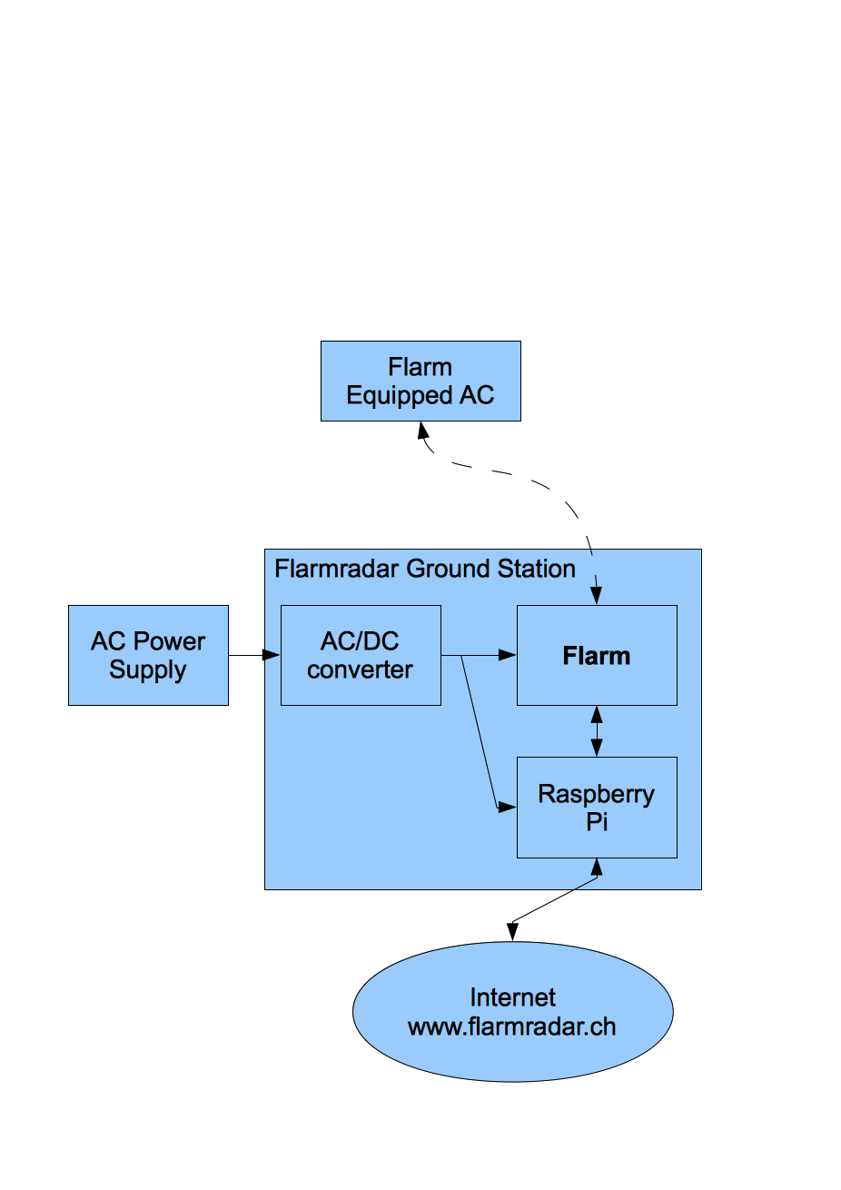
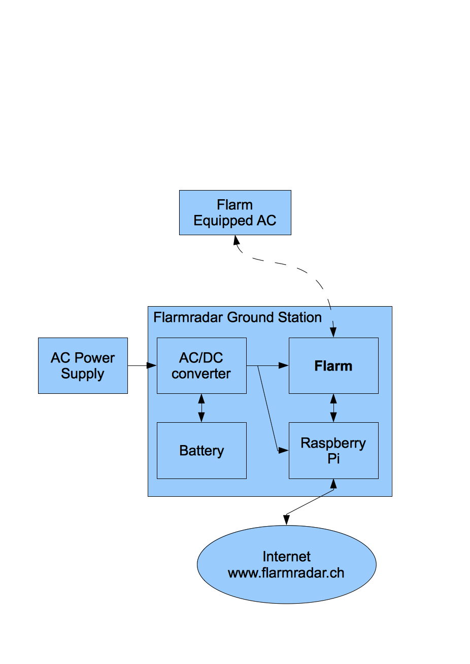
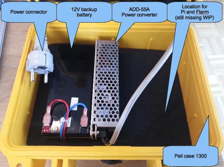
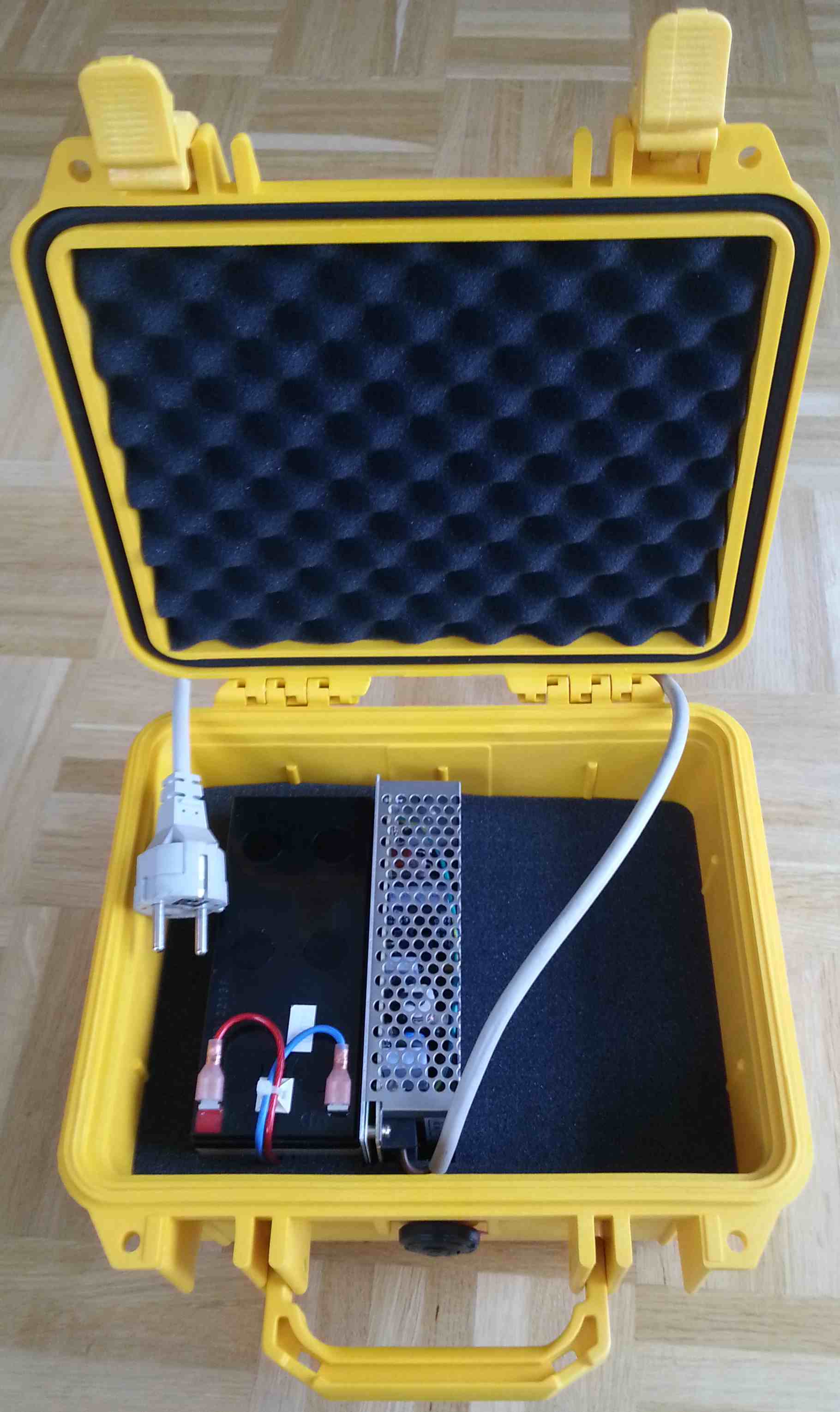
- All in one power supply: The Mean Well power converter ADD-55A offers 12V and 5V power output which can be run on standard power supply (88-264VAC) when available. If no power line is availble the device features a battery connection, which serves as backup power source.
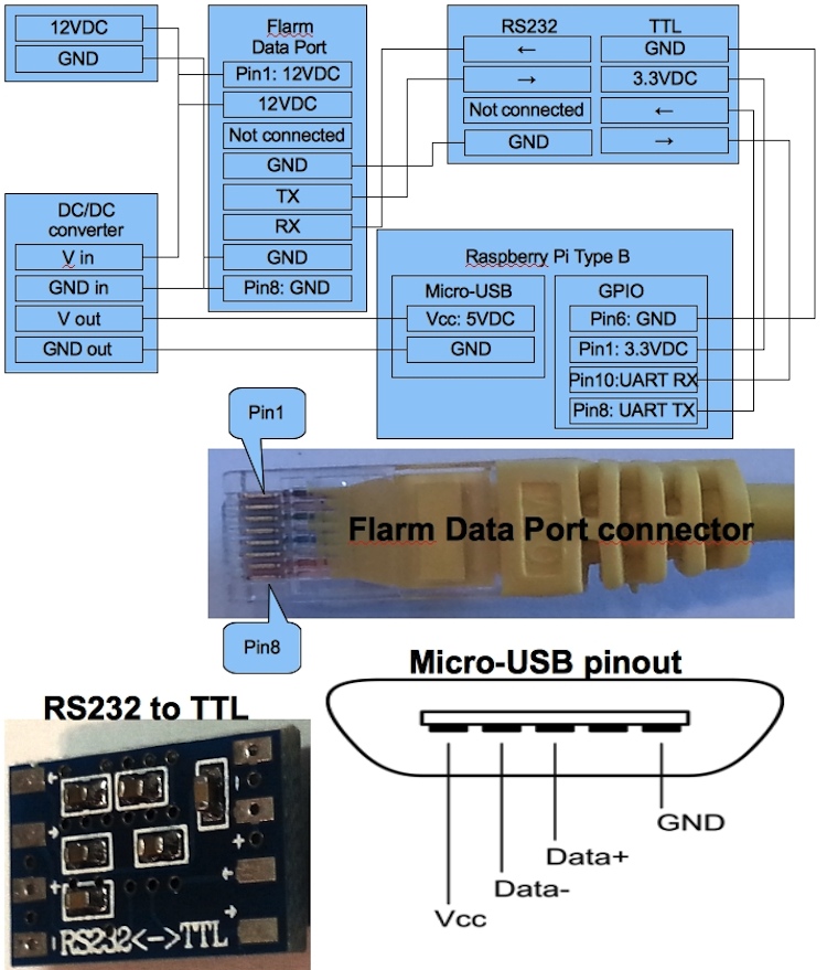
- Flarm <--> Pi Data connection
- Flarm delivers RS232 signal on its data port. To feed this signal into the Pi, there are presently two alternative ways of doing:
- RS232-USB-cable
- Buy a RS232 to USB converter cable. Preferable one which uses the FTDI chipset (e.g TBD). If you use a different chipset, this may not be supported by default by the Pi operating system.
- Attach the converter to your Flarm and to one of the USB connectors on the Pi
- Serial-In of the Pi
- The Pi features a serial interface (UART) on its GPIO pins.
- Pi's serial interface works on 3.3V. Hower, Flarm supplies higher signal levels. DO NOT CONNECT THE FLARM DATA LINES DIRECTLY TO THE PI'S GPIO PINS!!!
- Buy a RS232 to TTL level shifter (e.g. E-Bay - costs less than 2 EUR)
- Solder Flarm's TX, RX and ground (coming from the RJ45 jack) onto the RS232 side of the level shifter. Most level shifters have well labeled soldering pads
- Solder 4 wires to the TTL side of the level shifter. Ground, +3.3V, TX and RX need to be connected
- Buy a 2x13 IDC connector which attaches to the Pi's GPIO pin headers (e.g. RS-Online)
- Connect the four wires coming from the TTL side of the level shifter to the IDC connector. Pin layout depends on the version of your Pi. See GPIO Pins. If you have a revision 2 Pi, this is the pin connection: Pin1=+3.3V, Pin6=GND, Pin8=TX, Pin9=RX.
- Disable console output and boot messages on the serial interface. See here
- optional, recommended for a stationary installation: we use currently an external antenna
Knowledge & Troubleshooting
- Raspberry PI specific issues are collected on a separate page
Attachments (17)
-
Flarmradar_GS5.png (81.2 KB) - added by 12 years ago.
Two individual power supplies
-
Flarmradar_GS4.png (80.4 KB) - added by 12 years ago.
12VDC and DCDC converter
-
Flarmradar_GS3.png (80.5 KB) - added by 12 years ago.
ACDC converter with two voltages
-
Flarmradar_GS2.png (84.4 KB) - added by 12 years ago.
ACDC converter with backup battery
-
Flarmradar_GS_overview.jpg (191.7 KB) - added by 12 years ago.
Overview of Flarm radar ground station
- Flarmradar_GS_overview2.jpg (118.0 KB) - added by 12 years ago.
- Flarmradar_GS_peli1.jpg (157.3 KB) - added by 12 years ago.
- Flarmradar_GS_peli2.jpg (191.8 KB) - added by 12 years ago.
- Flarmradar_GS_peli2.2.jpg (219.2 KB) - added by 12 years ago.
-
Flarmradar_GS_wiring.jpg (211.5 KB) - added by 12 years ago.
Wiring description
-
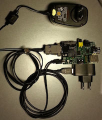
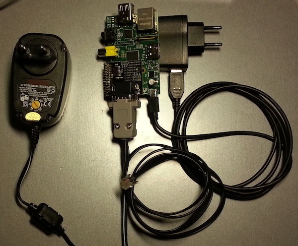
Pi_Converter_Cables.png (98.4 KB) - added by 12 years ago.
Pi with RS232 converter and cables
- Flarmradar_GS.jpg (18.3 KB) - added by 12 years ago.
- Pi_RS232_Converter.jpg (18.4 KB) - added by 12 years ago.
-
Pi_RS232_Cables.jpg (112.6 KB) - added by 12 years ago.
Pi with RS232 converter and cables
-
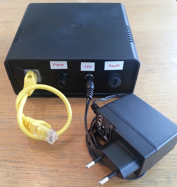
indoor_GS.jpg (102.3 KB) - added by 12 years ago.
Indoor Ground Station
-
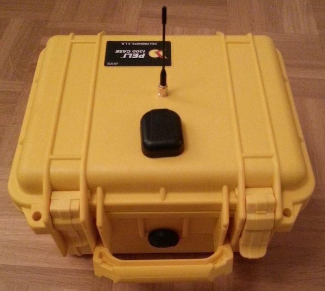
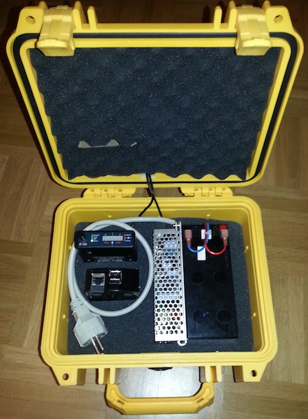
PeliFlarm1.jpg (100.4 KB) - added by 12 years ago.
Groundstation in Peli Case
-
PeliFlarm2.jpg (106.4 KB) - added by 12 years ago.
Groundstation in Peli Case
Download all attachments as: .zip